The Tanks
The Spirit of St. Louis has five fuel tanks and one oil tank. Two fuel tanks and the oil tank are located in the fuselage, while the other three fuel tanks are installed in the wing.
Each of the tanks in the original airplane were made from 'terneplate'. Terneplate is a form of tinplate; a thin steel sheet that has been coated with an alloy of lead and tin. Terneplate was particularly useful for storing flammable liquids, so it was the perfect choice for building fuel tanks with.
When the original Spirit of St. Louis was built, the ratio of tin to lead was about 10 or 20 percent tin to 80 or 90 percent lead. Today, traditional terne-plated steel is no longer available due to environmental reasons.
This meant that John had to find another metal he could use to build the tanks with. He chose galvanized steel which he purchased in full sheets that had to be cut to size.


John also purchased sheets of 3/4 inch plywood he used to cut "forming dies" with. These dies would allow him to roll the edges of the galvanized steel into smooth, rounded edges as he created the internal baffles the tanks would require.


The largest tank in the aircraft is located in the fuselage, just forward of the cockpit. This "main" fuel tank holds 257-gallons of fuel within four primary baffled 'chambers'. Each of the chambers are further divided in thirds by baffled 'walls'. These baffles help to keep all that fuel from 'sloshing' uncontrollably from side to side, or forward and aft, during flight.
John assembled and then riveted the interior baffled chambers and walls together to complete the internal structure of the fuel tank.

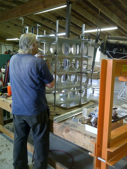
With the outer skin clamped in place to the internal structure, John drilled pilot holes through the outer tank skin and through the internal structure where the rivets would be driven to hold the skin in place. Clecoes were used to keep the pieces together as John methodically set each rivet in place around the tank skin.
Once all the rivets had been set, John began the job of soldering over every rivet in order to ensure there would be no leaks when fuel is finally introduced into the tank.


With both the forward and aft endskins in place, John attached the lower portion of the outer skin to the tank. He then built and installed the fuel filler neck to the upper end of the tank.

Then it was time to install the upper tank skin.
Wrapping the galvanized steel over the tank structure ... John once again drilled pilot holes and installed clecoes to hold the skin to the internal structure until he was able to rivet the skin on permanently.
By the time John got this far, he needed help. I spent several days in the shop bucking rivets for him since his arms were simply NOT long enough to reach around the tank!


It was also necessary for John to add fuel fittings to the tank where the fuel lines will attach once the tank is installed in the fuselage.
Once all the skins were riveted in place ... all the rivets soldered over ... all the edges of the tank soldered to ensure it was sealed ... John leak tested the tank with water.
We filled the tank to the very top with water and allowed the water to stay in the tank overnight.
As we emptied the tank the next day, we measured the output in order to know for certain how many gallons the tank could hold.
By the time the tank was empty, we had removed 257-gallons of water!
When it was clear the tank was secure and did not leak, John determined it was then ready for a coat of primer.
Once dry, we carefully lowered the tank down onto the wooden cradle that is attached to the lower fuselage framework.

After successfully constructing the main fuel tank, it was time for John to shift his attention to the forward fuselage fuel tank and the oil tank. Both of these tanks are positioned in the motormount, just forward of the main fuel tank.
The process was the same for the forward fuel tank and the oil tank as it was for the main fuel tank.
Full sheets of galvanized sheet metal ... 3/4 inch plywood cut into die blocks ... and lots of 'forming' to get each piece ready for assembly.
Both of these tanks provided a different challenge for John because their shapes were not only different from the main fuel tank he had just completed, but they were different from each other as well.
Both tanks are progressively smaller as their position in the fuselage is ever closer to the engine. They both taper from a larger profile at the back of the tank to a smaller profile at the front, in order to maintain the streamline slope from the leading edge of the wing, right on down to the propeller nose cone.

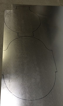

John made a cardboard template of the oil tank and installed it in the motor mount in order to ensure he got the measurements correct before laying the pattern out on the sheet of galvanized steel. He then formed the edges around the plywood die he had cut.


After completing the internal baffling, adding the outer skin, and installing the fittings and filler pipe, John weighed the oil tank ... just as he did with all of the individual parts he built for the aircraft.

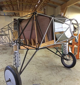

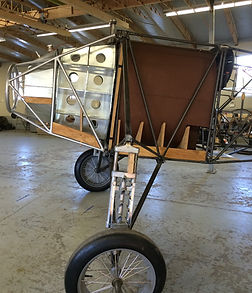
With the oil tank completed and in place, it was time to move on to the forward fuel tank. Periodically John would place the tank in the motor mount in order to ensure the "fit" was correct as the construction progressed.
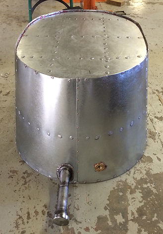
And finally, with the tank skinned and
fittings in place, John positioned the
forward fuel tank in the motor mount
just aft of the oil tank where it belongs.

With the fuselage tanks completed and installed, it was time for John to move on to the challenge of the three wing tanks. There is one fuel tank in the center of the wing over the cockpit, and two more on either side of the center tank, just outboard of the upper fuselage longeron.
Each of the wing tanks have 'channels' crossing through the tank diagonally from one corner to the other. These 'channels' allow the double sets of drag and anti-drag wires to extend through the fuel tanks and attach to the forward and rear wing spars on either side.
With no drawings to go by, and only damaged pieces of a Ryan M-1 wing fuel tank available to use as a pattern ... John figured out how to bend the sheets of galvanized steel to create the 'channels'.
The M-1 channels were constructed with a seam about half way up the side of each channel. John deviated from that design to make his channels with only one seam along the top. This design would drastically reduce the amount of fuel that could leak out in the case of a seam potentially coming apart.
More details on the way ...
Check back again soon ...
.jpg)
_JPG.jpg)
_JPG.jpg)
Follow these links for more:
Background Construction Authenticity Visiting the Original The Build Discoveries
Flights & Events Photo Gallery Facebook ~ #jnespirit JNE Aircraft~YouTube